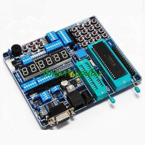
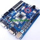
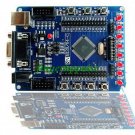
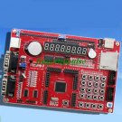
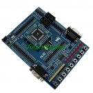
MCD-DEMO2---PIC 16F87X Microcontroller Development Board (Brand new)
The development board can be used for all PIC16XX/PIC18XX 28PIN or 40PIN PIN devices (except 16 F59)
Ideal for the Student or Hobbyist to start developing and testing your PIC projects with this multi-featured and flexiable PIC Development board.
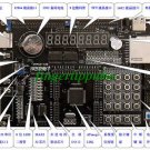
PIC 16F87X Development board 2 consists of :
1. 8 indicator LEDS
2. ICD2 Header connector for programming / Debugging with Microchips ICD2
3. 16x2 LCD Character display
4. 6 Seven segment display
5. RS232 Serial communication port
6. 16 button matrix Keypad
7. Stepp motor slot
8. 4 push buttons
9. Infrared reception
10. DB9 connector and RS232 Transeiver (for serial Comms)
11. I2C Serial EEprom 24c01B - dipswitch used for write enable and setting device address (on supported eeproms)
12. 2 pin sockect for main Osc (4MHz resonator -Default) allows for easy changing of the main Osc frequency. Provion for loading caps if using a crystal.
13. Buzzer
14. Reset switch
15. Uncommited PIC I/O ports - So the PIC's I/O lines may be connected to any of the onboard modules or external circuits
On-board resources:
4*4 Matrix keyboard – to test password lock and other items.s. Buzzer voice/PWM output experiment – to practice normal voice, music and PWM output sound. 5-way independent key-press–for easy various key-press input experiments.
RS-232 communication for connection with a PC or any other device with a DB9 connector
Infrared remote-control receiver – to practice infrared remote-control decoding and all kinds of infrared remote control.l.
All I / O output to facilitate expansion IIC (I2C) communication – to read/write 24CXX series chips with hardware IIC or software IIC directly. SPI communication–to read/write EEPROM of 93CXX with hardware SPI or software analog SPI,to select 8-bit or 16-bit read/write method through jumper.
Clock selection – jumper for switch between various oscillation modes, to replace crystal vibration of different frequency as required by development of product.
DS18B20 digital temperature sensor – 1-wire bus communication, wide range for temperature measurement, high accuracy and sensitivity (remark: chip DS18B20 is optional). Stepper motor driver circuit(remark: Setpper motor is optional). Simulation debugging interface – to directly connect ICD1/ICD2/MCD1/MCD2 and carry out on-line simulation for on-board chips and resources
On-board power module – can connect to the polarity of external AC or DC power supply optionally, voltage range 7-12V mcu/mpu reset key 1-way A/D converter signal input. 8-way independent LED
12864-character LCD–128*64 lattices.
1602-character LCD–internal 5*7 lattices, to display 16*2-character.
6-bit 7-segment digital tube – to realize dynamic or static display experiment of digital tube, to display clock,temperature or to make counter.
Sample with C and ASM Program sources code as below (using pic16f877a):
DS1820
Buzzer
128x64 GLCD (See the following Photos)
1602 LCD (See the following Photos)
93C46
24C02
4x4 Key testing
8x LED
7x Segment
ADC
Infrared Remote
stepp motor
The package includes
1. MCD-DEMO2--PIC 16F87X Microcontroller Development Board
2. Power supply(110-240 AC TO 9V DC)
3. Serial Cable
4. 1 x RJ12 Connection Cable
5. 16F877A Chip
6. 1602 LCD with backlight
7. CD-ROM (Development PCB Layout,Development Board Schematic,Sample code (C / ASM) for each onboard module, MPLAB 7.50 .)
TE54